Arduino UNO R4 Minima Digital-to-Analog Converter (DAC)

Learn how create waveforms and output them on a piezo, using the DAC on the UNO R4 Minima board.

The Arduino UNO R4 Minima has a built in DAC (Digital-to-analog Converter) which is used to transform a digital signal to an analog one. This feature can be used to build a plethora of fun audio projects, but also work as professional lab equipment as a cheap function generator, for example.

Goals

In this article, you will learn:

  • about the DAC feature onboard the UNO R4 Minima,
  • differences between PWM and DAC techniques,
  • how to generate a waveform (sine),
  • how to output this waveform on a piezo speaker.

Hardware & Software Needed

To follow along with this article, you will need the following hardware:

Circuit

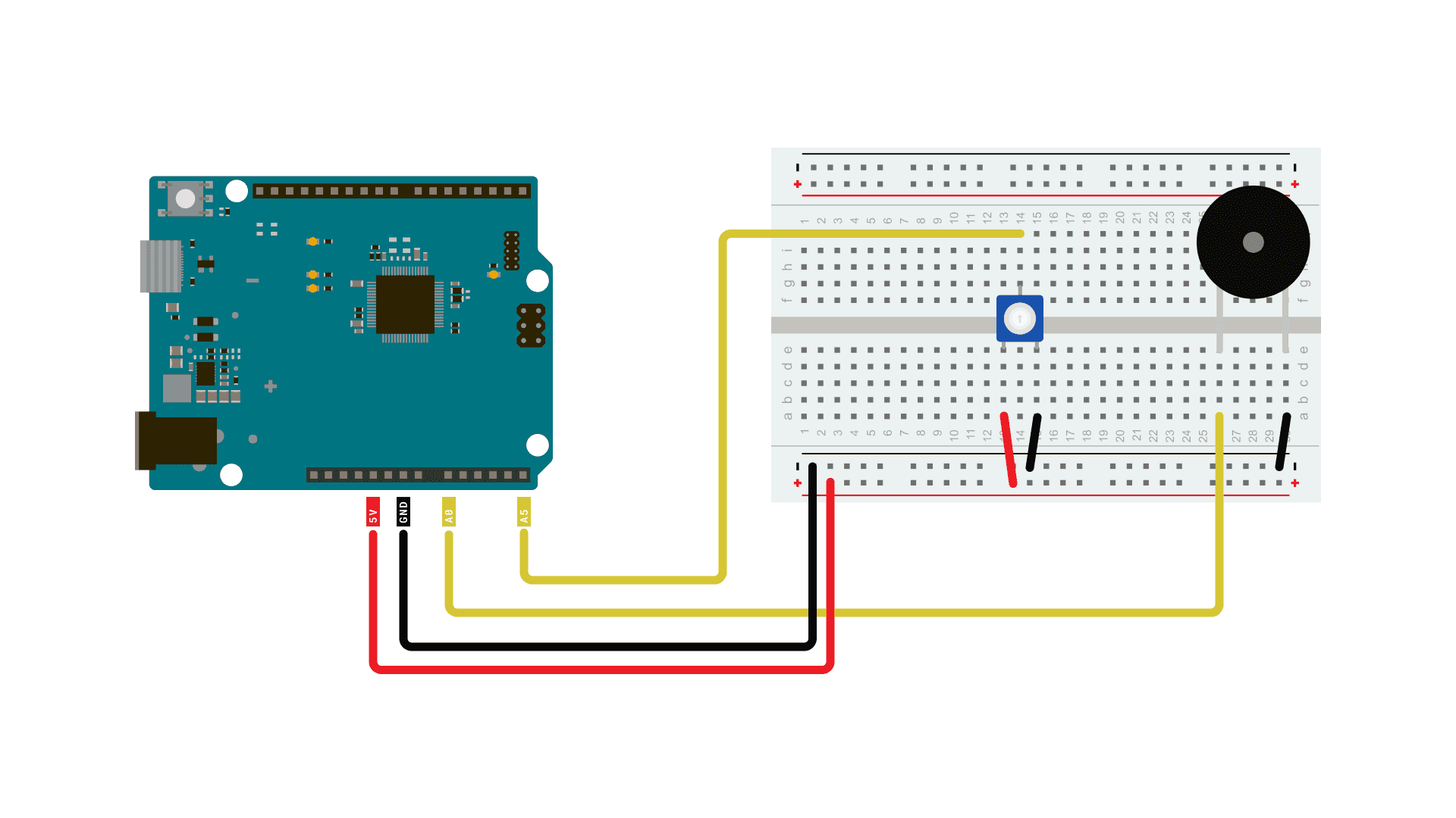
The circuit required for this tutorial can be found in the diagram below:

Piezo buzzer connected to UNO R4

Analog Output vs PWM

For many use cases when analog output is required, using PWM (Pulse Width Modulation) instead of genuine analog output will yield essentially the same results. A digital output pin can only either be fully on (HIGH) or fully off (LOW), but by turning it on and off very quickly with precise timings, the average voltage can be controlled and emulate an analog output. This method is called PWM.

For example when dimming an LED, you can freely use a PWM enabled digital pin as an analog output pin and the LED would dim just the same as if you'd be using a DAC output.

However this will not always be the case, and for many uses you will need to use a genuine analog output to get your desired results. One such case is in audio purposes, where a PWM output simply will not give the same quality of sound as a genuine analog output, and requires some fiddling to work in the first place.

Code

The code for this tutorial is split in two parts, one main sketch and a header file containing a pre-generated sawtooth-waveform.

With this sketch, we have pre-generated a sine waveform. You could also dynamically generate it either at the beginning of your sketch or during, but doing so would be less efficient without gaining any performance. So going this route is the best practice.

The waveform is being stored as samples in an array, and with every loop of the sketch we'll update the DACs output value to the next value in the array.

Open a new sketch and paste the following code into your window.

Code Source on Github
1/*
2 SineWave
3
4 Generates a pre-generated sawtooth-waveform.
5
6 See the full documentation here:
7 https://docs.arduino.cc/tutorials/uno-r4-wifi/dac
8*/
9
10#include "analogWave.h" // Include the library for analog waveform generation
11
12analogWave wave(DAC); // Create an instance of the analogWave class, using the DAC pin
13
14int freq = 10; // in hertz, change accordingly
15
16void setup() {
17 Serial.begin(115200); // Initialize serial communication at a baud rate of 115200
18 wave.sine(freq); // Generate a sine wave with the initial frequency
19}
20
21void loop() {
22 // Read an analog value from pin A5 and map it to a frequency range
23 freq = map(analogRead(A5), 0, 1024, 0, 10000);
24
25 // Print the updated frequency to the serial monitor
26 Serial.println("Frequency is now " + String(freq) + " hz");
27
28 wave.freq(freq); // Set the frequency of the waveform generator to the updated value
29 delay(1000); // Delay for one second before repeating
30}

Testing It Out

Once you have uploaded the code to the board, it should start generating a sine wave oscillation on the DAC, that depending on the frequency could be used to produce sound on a piezo buzzer or speaker. If you have an oscilloscope at hand, connecting its probe to the DAC output might be an interesting exercise so see what the wave looks like.

Now try twisting the potentiometer, and listen to how the sound changes.

Analog Wave Types

The sketch above generates what is known as a sine wave. It is called a sine wave because if you were to plot the voltage against time, you'd notice that the line looks just like a sine function.

There are other types of analog waves that will produce a distinctly different type of sound compared to a sine wave. The library we're using in this sketch also allows you to create sawtooth and square waves. These types of wave also gets their names from how they look when the voltages are plotted against time.

Try changing the wave type and listen how it changes the feel of the sound.

Change the wave by replacing Line 18 in the sketch "

wave.sine(freq);
" with either

1wave.square(freq);

or

1wave.saw(freq);

Now that you know your setup is working, you can experiment further with different examples and see how you can use the DAC of the UNO R4 to generate sounds and even melodies.

Note: In this setup, we're just using a piezo buzzer, you may notice that the sounds it's making are pretty faint. If you want to fix this you'll need a 4 or 8 Ohm speaker, and an amplifier. You can find many breakout amplifier modules that are easy to use online.

Frere Jacques

This one for example plays the melody of Frere Jacques:

Code Source on Github
1/*
2 DAC Melody player
3
4 Generates a series of tones from MIDI note values
5 using the Uno R4 DAC and the AnalogWave Library.
6 The melody is "Frere Jacques"
7
8circuit:
9 * audio amp (LM386 used for testing) input+ attached to A0
10 * audio amp input- attached to ground
11 * 4-8-ohm speaker attached to amp output+
12 * Potentiometer connected to pin A5
13
14 created 13 Feb 2017
15 modified 3 Jul 2023
16 by Tom Igoe
17
18 See the full documentation here:
19 https://docs.arduino.cc/tutorials/uno-r4-wifi/dac
20*/
21#include "analogWave.h"
22analogWave wave(DAC);
23
24#define NOTE_A4 69 // MIDI note value for middle A
25#define FREQ_A4 440 // frequency for middle A
26
27// the tonic, or first note of the key signature for the song:
28int tonic = 65;
29// the melody sequence. Note values are relative to the tonic:
30int melody[] = {1, 3, 5, 1,
31 1, 3, 5, 1,
32 5, 6, 8, 5, 6, 8,
33 8, 10, 8, 6, 5, 1,
34 8, 10, 8, 6, 5, 1,
35 1, -4, 1,
36 1, -4, 1
37 };
38// the rhythm sequence. Values are 1/note, e.g. 4 = 1/4 note:
39int rhythm[] = {4, 4, 4, 4,
40 4, 4, 4, 4,
41 4, 4, 2,
42 4, 4, 2,
43 8, 8, 8, 8, 4, 4,
44 8, 8, 8, 8, 4, 4,
45 4, 4, 2,
46 4, 4, 2
47 };
48// which note of the melody to play:
49int noteCounter = 0;
50
51int bpm = 120; // beats per minute
52// duration of a beat in ms
53float beatDuration = 60.0 / bpm * 1000;
54
55void setup() {
56// start the sine wave generator:
57 wave.sine(10);
58}
59
60void loop() {
61 // current note is an element of the array:
62 int currentNote = melody[noteCounter] + tonic;
63 // play a note from the melody:
64 // convert MIDI note number to frequency:
65 float frequency = FREQ_A4 * pow(2, ((currentNote - NOTE_A4) / 12.0));
66
67 // all the notes in this are sixteenth notes,
68 // which is 1/4 of a beat, so:
69 float noteDuration = beatDuration * (4.0 / rhythm[noteCounter]);
70 // turn the note on:
71 wave.freq(frequency);
72 // tone(speakerPin, frequency, noteDuration * 0.85);
73 // keep it on for the appropriate duration:
74 delay(noteDuration * 0.85);
75 wave.stop();
76 delay(noteDuration * 0.15);
77 // turn the note off:
78 // noTone(speakerPin);
79 // increment the note number for next time through the loop:
80 noteCounter++;
81 // keep the note in the range from 0 - 32 using modulo:
82 noteCounter = noteCounter % 32;
83
84}
85

MIDI Piano Notes

This sketch will break down the potentiometer input to steps, that are translated to the 88 MIDI notes that represent the keys on a piano.

Code Source on Github
1/*
2 Plays a tone in response to a potentiometer
3 formula from https://newt.phys.unsw.edu.au/jw/notes.html
4 and https://en.wikipedia.org/wiki/MIDI_tuning_standard:
5
6 the MIDI protocol divides the notes of an equal-tempered scale into
7 128 possible note values. Middle A is MIDI note value 69. There is
8 a formula for converting MIDI note numbers (0-127) to pitches. This sketch
9 reduces that to the notes 21 - 108, which are the 88 keys found on a piano:
10
11 frequency = 440 * 2^((noteNumber - 69) / 12.0)
12
13 You can see this applied in the code below.
14
15 circuit:
16 * audio amp (LM386 used for testing) input+ attached to A0
17 * audio amp input- attached to ground
18 * 4-8-ohm speaker attached to amp output+
19 * Potentiometer connected to pin A5
20
21 created 18 Dec 2018
22 modified 3 Jul 2023
23 by Tom Igoe
24
25 See the full documentation here:
26 https://docs.arduino.cc/tutorials/uno-r4-wifi/dac
27*/
28
29// include the AnalogWave library:
30#include "analogWave.h"
31analogWave wave(DAC);
32
33// middle A is the reference frequency for an
34// equal-tempered scale. Set its frequency and note value:
35#define NOTE_A4 69 // MIDI note value for middle A
36#define FREQ_A4 440 // frequency for middle A
37
38const int speakerPin = A0; // the pin number for the speaker
39void setup() {
40 Serial.begin(9600);
41 wave.sine(10);
42}
43void loop() {
44 // convert sensor reading to 21 - 108 range
45 // which is the range of MIDI notes on an 88-key keyboard
46 // (from A0 to C8):
47 int sensorReading = analogRead(A5);
48 int noteValue = map(sensorReading, 0, 1023, 21, 108);
49 // then convert to frequency:
50 float frequency = FREQ_A4 * pow(2, ((noteValue - NOTE_A4) / 12.0));
51 int freq = int(frequency);
52 // turn the speaker on:
53 wave.freq(freq);
54 Serial.print("note value: "+ String(noteValue) + " freq: ");
55 Serial.println(freq);
56 delay(500);
57}
58

Conclusion

By following this tutorials you've experimented with the DAC on the Arduino UNO R4 boards and used it to first generate a sine wave, then to explore the possibilities of analog output by testing out various examples.

Suggested changes

The content on docs.arduino.cc is facilitated through a public GitHub repository. You can read more on how to contribute in the contribution policy.

License

The Arduino documentation is licensed under the Creative Commons Attribution-Share Alike 4.0 license.